|
||||
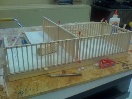
Bottom Floor: 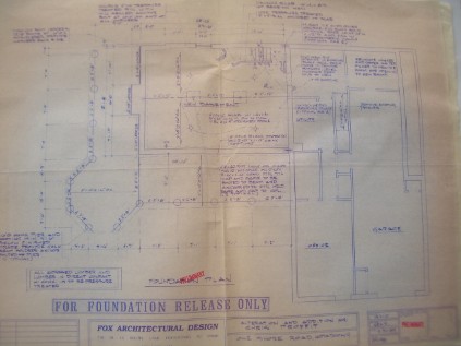
I had to make some alterations to my design in CAD because the walls in the blueprint weren't to scale of the balsa wood I was using and also there was construction that had been done on my house since the blueprints were made (i.e my room was added on to the top floor in addition to the first three and a skylight that extends from my room to the dining room which is unlabeled in the top floor blueprint)
Bottom Floor: 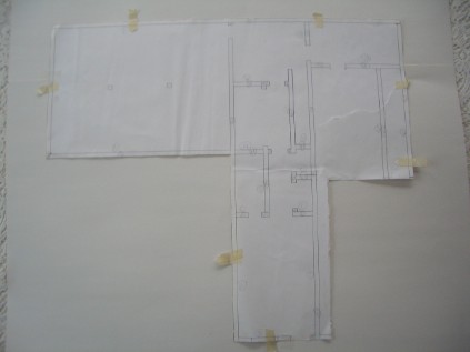
First I started with a sturdy base to secure it, framed it and added my floor joists. Then I cut out the blue print to pin it onto the floor and try to map out which walls would overlap eachother and where. (which is why there is tape and numbers on the CAD drawings.)
Bottom floor: 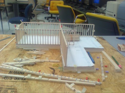 When the garage side was added: 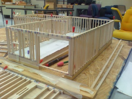
I ran into a bit of a problem when I added the top floor. I wanted my viewers to be able to remove the top to view all of my hardwork on the bottom floor. So since I wasn't securing the base permanently, I had to complete the top floor on a temporary base then add it to the top of the bottom base later on. I used a foam poster board as my temporary base.
Top floor: 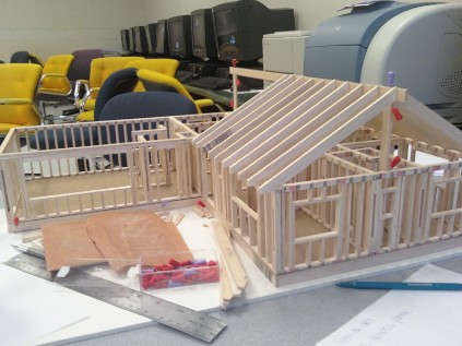
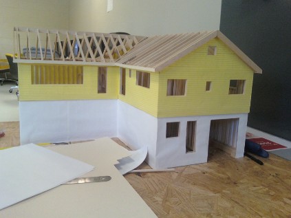
The next step in my process was to add the siding of my house. Since my house was added onto so much throughout the years, the siding fluctuates as you navigate around the house. The skylight was added on later so the outside walls around that area is all brick while the other areas are yellow siding and white painted cement. I found paper that most closely related to these patterns to simulate the real outside of my house.
 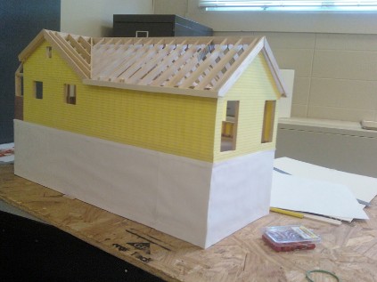
The last step in my process was to add my deck and also the roof. I was upset the roof, roof joists, and ceiling joists would cover my hard work on all of the small detailed walls on my first floor so I requested from the teacher that I could build the roof with a hinge so viewers are able to lift it up and look into the house from up top. He approved but recommended I still leave a spot on my roof where passerbys can admire my roof joists just incase they didnt want to touch the model.

This house remains to be my pride and joy of any project I have ever done at Penn State. If I had more time I would have elaborated on the doors and windows (especially the bay wondows) and also tryed to simulate my irregular yard. The most difficult part of this project was probably trying to figure out how I was going to make my top story removable and also making the transition to a new base (the foam poster). The most difficult part of that was redoing a frame, adding floor joists to it, and trying to keep the frame in line with the CAD drawing and that's hard to do when the frame isn't glued and secured into place. |
Top Floor: 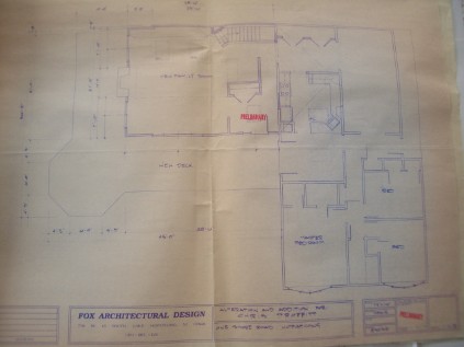
Top Floor: 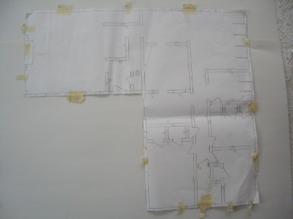
 When the walls on the bottom floor were completed: 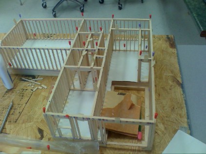
As you can see in this step I also began to add ceiling joists and roof joists.
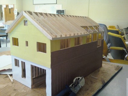
My house in New Jersey is right on Lake Hopatcong, so the back of my house (the white part) is buried since it is built on a hill which it why there is access to my garage and downstairs in only the front of the house. It is also why the stairs of the deck look unfinished. |
|||